Calculating Isometric Angles From Blender Cameras
If you don’t want to read, you just want to use the calculations, go straight here:
One of my favourite styles of illustration is without a doubt Isometric. What characterizes isometric art is that, unlike with normal perspective-based art with perspective lines that converge, the perspective lines in an isometric piece are completely parallel. A typical isometric scene illustrates the inside of some room or some building.

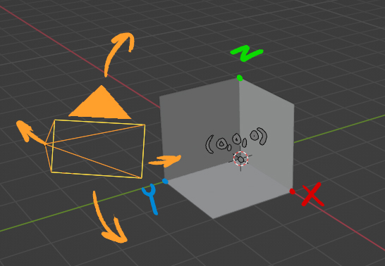
You’re looking at the inside of a box, essentially - consider the “upsidedown Y” that defines the inside corners of this box. The standard way to set up an isometric image is so that the angle between each edge of this Y is 120°. If you want to set up a Blender scene according to these standards, the general advice is to set up an orthographic camera with rotation of (54.736,0,45), but here’s an interesting question: what if you have a reference image, or want to make an image yourself, with different angles? Not all isometric images have this 120° relationship - you can have an isometric angle of this room with the camera placed at just about any angle.
I was producing an isometric illustration myself using a reference with a non-standard angle, and I wanted to figure out how I could get my Blender camera to match it, so naturally I googled a bit, and found no answers (but a couple other people asking), so I asked the question myself. I got no answer for about a week, so I took it upon myself to figure it out. I hadn’t done any maths more complex than basic algebra in the last 10 years, nevermind 3d trigonometry, but… how hard could it be?
I realized that it’s probably easier to figure it out in reverse - given a particular camera rotation, how will the upsidedown Y angles compare to each other? My first thought process was, given a “unit room” - a room whose back corner starts at (0,0,0) and whose “upsidedown Y” extends 1 unit in each direction, I can project that onto the plane of any camera with any given rotation, and then convert the points of that plane onto a plane which is perfectly flat - a plane whose normal is [0,0,-1] for example.

I started some googling to figure out how to do that, and I made a plan based on these two links: where will a vector intersect a plane? and how to rotate a vector. The plan was this: figure out the normal vector of my camera angle, then using the 4 points of the “unit room” as an origin point, go from each of those points using the normal vector to figure out where on the camera plane that point will be rendered. After that, I’ll have the 3 vectors of my ‘upsidedown Y’, and I can use the second link to rotate each of those vectors onto a flat plane - the rest of the work should fall into place after that.
But after thinking about it for a while, I realized: rather than projecting onto a rotated camera plane, and then “unrotating” the plane, it might actually be easier to unrotate EVERYTHING, including the unit room, from the start, and then do the much simpler job of projecting that unto the flat plane. From there, I could figure out the angles between the upsidedown Y lines (as well as the relative lengths of them).
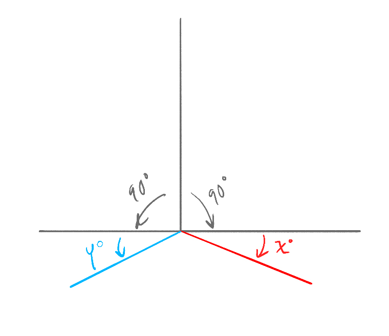
So, that’s exactly what I did here – plug in the x and z rotation of a blender camera (probably only works with angles between 1 and 89), and I get the relative angles and lengths. I’ll work this into a UI soon. In case it’s not clear, the actual final angle measurements given in Step 3 are illustrated by this:

Fun fact: it matters in what order you do the rotations. Rotating X -54.736 and then Z -45 produces a different result than doing Z and then X.
The final result of all these calculations, synthesized into a UI, can be found here: